Unfortunally I noticed to late that the launchpad their msp430 devices have no hardware UART, so I had to look for a solution.
I decided to stay in the msp430 family and my eye felt on the MPS430F2132, it has the following benefits;
1x Hardware UART
1x Hardware I2C
2x timers (ideal to control my TEC's)
28 pins instead of 14 or 20
more flash
So, a tiny shield that can be mounted on the launchpad is under construction, and I hope it will be ready by friday :).
It is a shield because I want to be able to easily program and debug it, and since it has some more I/O's I added some features.
1x RGB led
1x usb-rs232 converter (these pins are on port 3)
1x buzzer
5x header for I2C
The sad thing is that I have to redesign my protoshield because the I2C pins no longer match...
woensdag 6 april 2011
donderdag 10 februari 2011
Mini-Tutorial 1; Blink-a-LED
Today I finally managed it to get my CCS version (code composer studio) working, it was stuck somewhere with the updating system, after reinstalling it, it finally worked =)
I haven’t done a lot, but I know how the basic works (at least I hope) and I fully commented the demo blink-a-led application so I know exactly what every instruction does.
The you can download the demo code from the site of TI (look for slac463a.zip) and the 'lab 1: Blink launchpad's leds' pdf written by Adrian Fernandez can be found here.
//******************************************************************************
// MSP430G2xx1 Demo - Software Toggle P1.0
//
// Description; Toggle P1.0 by xor'ing P1.0 inside of a software loop.
// ACLK = n/a, MCLK = SMCLK = default DCO
//
// ***code cut***
//
// D. Dang
// Texas Instruments, Inc
// October 2010
// Built with CCS Version 4.2.0 and IAR Embedded Workbench Version: 5.10
//
//Remade and comments added by watchout3
// mailto:
// watchout.3
// ***anti spam line*** tralalalaa
// @hot
// ***anti spam line*** badaboem
// mail.com
//
//******************************************************************************
#include <msp430g2231.h>
void main(void)
{
//****************************************************************
// PROGRAM INITIALISATION
//****************************************************************
WDTCTL = WDTPW + WDTHOLD; // Stop watchdog timer
// See user manual (slau144f) p. 360
P1DIR |= 0x01; // Set P1.0 to output direction
P1DIR |= 0x40; // Set P1.4 to output direction
// If you wish to set a single bit to '0' without changing the state
// of the other bit-registers, you have to perform a "OR"-operation.
//
// You can do this on 2 ways, the short or the long one
//
// P1DIR |= 0x01; (short) (0x01 = bin "0000 0001")
// P1DIR = P1DIR | 0x01 (long )
//
// which results in xxxx xxx1 (where x means no state change)
// If you wish to reset a single bit to '1' without changing the state
// of the other bit-registers, you have to perform a "AND"-operation.
//
// P1DIR &= 0xFE (short) (0xFE = bin "1111 1110")
// P1DIR = P1DIR & 0xFE (long )
//
// which results in xxxx xxx0 (where 0 means no state change)
P1OUT = 0x40; // The two leds will toggle each on their turn
// ***Chose only one of both!!!***
//P1OUT = 0x00; // The two leds will toggle together
// You must preset the output registers.
// When you are debugging with your IDE open and don't repower the target aka
// launchpad (disconnect and reconnect it) the output registers won't be resetted.
//
// This will cause an unpredictable 'boot-up' state of the outputs (in my case they
// didn't toggled together)
//
// Probaly this comes beacause the ram is volatile memory witch only loses it's state
// when the power is shutted off (a reset didn't helped in my case)
//
// Also I noticed a sort of 'bug' when you go in debug mode and upload the code to your
// device, the reset ain't working until you remove the VCC jumper (once placed back
// the reset won't work anymore), remove the RST/TEST-jumpers or again, fully disconnect
// the device so the PC connection is interrupted
// Which method the correct one is, I don't know...
//****************************************************************
// MAIN PROGRAM
//****************************************************************
for (;;) // Start the infinitive loop
{
volatile unsigned int i;
// Reserving RAM memory
i = 50000; // Delay
// I suggest to initialise the memory as fast a s possible and not 'somewhere' in the code,
// because the possible errors like I mentioned above.
P1OUT ^= 0x01; // Toggle P1.0 using exclusive-OR (0x01 = bin 0000 0001)
P1OUT ^= 0x40; // Toggle P1.4 using exclusive-OR (0x40 = bin 0000 1000)
// Logic Table of an 'EXOR' function
//
// Input||Output
// A B || Q
//------||----
// 0 0 || 0
// 0 1 || 1
// 1 0 || 1
// 1 1 || 0
do (i--); // Delay function, increase 'i' aslong it is not differs from 0
while (i != 0); //
}
}
woensdag 2 februari 2011
launchpad DevBoard
During the weekend I made a small development/proto board.
It has the following features:


It has the following features:
- Small breadboard for quick and easy prototyping
- 2 power sockets on each side (2x GND/side + 2x Vcc/side, each side is decoupled with a 100nF cap)
- A I2C temperature sensor (TMP100), probally we will be using this type of sensor to measure the temperature of the peltier element.
- Pull-Up resistors for a proper I2C communication.


The sensor can be disconnected by 2 jumper pins, it is an SMD device, but if you wish you can also use a DIP version, Maxim-IC has some nice I2C temp sensors in DIP backage (we use this one because of the TI ADC ;) )
I also want to add a power LED (just because it looks cool) and mayby a RGB led to train my PWM skills and to show if the temperature is rising/falling.
dinsdag 25 januari 2011
It's alive!
Actually only the demo app that was preloaded in my launchpad is alive.
But it was a pain in the ass.
First I started with installing all the IDE's (there are 2 available), and then i wanted to check out the demo application.
But in my rush I forgot to instal the drivers for the launchpad... |:(
So if you are planning to use this make sure you do the next things:
1) Instal the IDE you want to use
2) Connect th launchpad to your PC
3) your PC will ask if he needs to search for drivers, make sure you can select were
4) Select "\ccsv4\emulation\drivers\msp430" (windows (even vista) will select the correct driver, so don't worry about that)
5) run the demo GUI you can find at he site of TI
6) That's it =).
This is how it looks :p

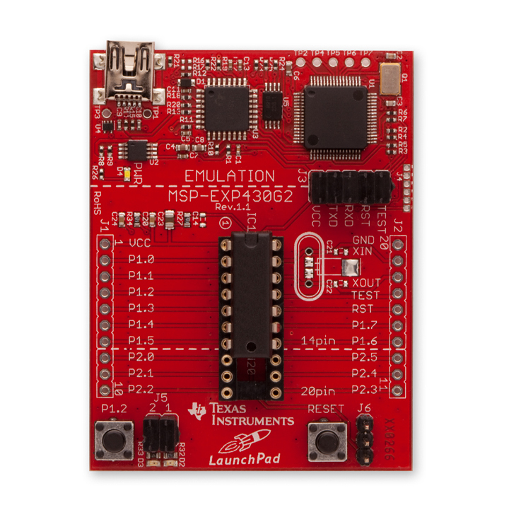
TI msp430 launchpad arrived! :)
I have some good news to anounce, today my order of TI's ADC arrived.
A first look tells me we have a potential winner were we can implement our PID controller in ;)
So the next few days I will do some 'experiments' with the launchpad to figure out how the IDE works and see what kind of stuff I can make with the launchpad.
Here is a picture of the launchpad:
 To be continued... ;)
A first look tells me we have a potential winner were we can implement our PID controller in ;)
So the next few days I will do some 'experiments' with the launchpad to figure out how the IDE works and see what kind of stuff I can make with the launchpad.
Here is a picture of the launchpad:
zondag 23 januari 2011
Peltiers revealed

A Peltier element is a small device which basically transfers heat or cold from one side to other side.
In the industry they are widely used to cool laser modules because the wavelength depends of the temperature.
And since they are becoming cheaper and easier to get also computer enthusiasts are using them to cool their pc in the hope to get better performance.
And since they are becoming cheaper and easier to get also computer enthusiasts are using them to cool their pc in the hope to get better performance.

By applying a low voltage DC power source to a Peltier element, heat will be moved through the module from one side to the other.
One module face, therefore, will be cooled while the opposite face simultaneously is heated.


Controlling a Peltier element

In many applications customers prefer to use PWM control. It means simple electronics and simple logical control.
At high frequency PWM the averaged current delivered to controlled object is estimated as equivalent of DC current of the same value.
It is true for many applications, but is a great mistake in a case of TECs.
TEC controlled by PWM operates less effectively than at DC current.
The PWM control is always less effective than TEC operation at the same average DC current and power consumption.
Neither are relays suitable to control Peltiers, these will cause a reduction of the TEC’s life time and you can’t exactly control the temperature of them, it will fluctuate too much.


Another important design note is that Peltier elements must always be cooled on their “hot”-side.
Otherwise you run the risk that you damage the Peltier by melting the internal solder.
Sources:
http://www.tec-microsystems.com/EN/Intro_Thermoelectric_Coolers.html
http://www.memmert.com/tekhnologii/koncepcija-temperaturnogo-kontrolja/sistema-nagrevaokhlazhdenija/
http://www.rmtltd.ru/tec_app_tips.htm
http://www.silram-cor.co.il/gp.asp?gpid=56
zaterdag 22 januari 2011
TI’s ADC part II + sample requests
The past few days I have been pretty busy.
First of all, we are allowed to participate to TI’s “Analog Design Contest” AND the Evaluation Modules (2x MSP430 + some other stuff) I requested will be delivered soon =).
First of all, we are allowed to participate to TI’s “Analog Design Contest” AND the Evaluation Modules (2x MSP430 + some other stuff) I requested will be delivered soon =).
While I was searching on Google for some information about Peltiers I suddenly came up to an application note of MAXIM-IC.
And their I discovered that they have made some IC’s especially for controlling Peltiers, in the app note was also a PID regulation drawn and explained.
So I sent some sample requests to rebuild the PID controller of the app-note:
And their I discovered that they have made some IC’s especially for controlling Peltiers, in the app note was also a PID regulation drawn and explained.
So I sent some sample requests to rebuild the PID controller of the app-note:
· MAX4475ASA OpAmp, Low-Noise, Low-Distortion
· MAX4477ASA OpAmp, Low-Noise, Low-Distortion
· MAX1968EUI Power Drivers for Peltier TEC Module up to 3A
· MAX1969EU Power Drivers for Peltier TEC Module up to 6A
More info can be found here:
http://www.maxim-ic.com/app-notes/index.mvp/id/3318
http://www.maxim-ic.com/app-notes/index.mvp/id/3318
Once I sent the sample requests I noticed that they also made Evaluation Modules exactly like in the app-note, but I wasn’t able to find the pricing/dealers.
SO I send a mail to MAXIM-IC for some more information about their Peltier-EVM’s
More info (except pricing…) can be found here:
http://www.maxim-ic.com/datasheet/index.mvp/id/3559
SO I send a mail to MAXIM-IC for some more information about their Peltier-EVM’s
More info (except pricing…) can be found here:
http://www.maxim-ic.com/datasheet/index.mvp/id/3559
If we can use this, we basically only need to make a descent mechanically construction and find a good DAC, but we only need to concern ourselves about the first because at school they have a DAC of NI that can be used together with labview.
Afterwards I discovered that TI also made some IC’s for driving Peltiers. So I began to search a little more on their site and this is what I sampled at TI:
maandag 17 januari 2011
Project specifications + TI’s “Analog Design Contest”.
Yesterday I have been mailing around to get some more information about what we may use from the previously posted open-source projects.
And what the requirement are of the system we need to design.
There are some tricky things (not blowing up the peltier, labiew interface, …), but I think we will over win them J
First something about the specifications of the system we need to design.
Also I have sent a mail to Texas Instruments to participate their “Analog Design Contest”, more info about this can be found here:
http://www.ti.com/ww/eu/university/analog_design_contest.html
This contest has some very cool features, you can get for 100$ of development tools and you can sample some free samples of their IC’s (that was already possible when you made an account on their site).
And if you are really going for it you can win some $$$ !!!.
The only thing you need to do for that is;
The analog IC’s may be chosen from the following categories:
So this won’t be a problem because we need at least one temperature sensor and a ‘switch’ to control the Peltier.
Also some Power Management Devices might be useful in our project to power the µC.
And the most beautiful part of it all, they have a small µC board (the msp430) that has a build in USB interface (I bet that it has some chips onboard to emulate a virtual COM port ;) ) for only 4,3$.
More info + a video about it can be found here:
https://estore.ti.com/MSP-EXP430G2-MSP430-LaunchPad-Value-Line-Development-kit-P2031.aspx
And what the requirement are of the system we need to design.
There are some tricky things (not blowing up the peltier, labiew interface, …), but I think we will over win them J
First something about the specifications of the system we need to design.
· The temperature needs to be regulated stepless over a region from 10°C to 70°C.
· The temperature must be regulated to a certain temperature within 5seconds, or if this is not possible, as fast as the Peltier can go.
· It doesn’t has to run stand alone, but it is a bonus point =)
· Additional sensor/actuators may be used, but are not necessary (i.e. a 7-segment display to monitor the temperature)
· So far we have no limitation in the mechanical part (the height, width, depth, used materials, …)
· We are free to chose the µC and which program we want to use to make the GUI on the PC
http://www.ti.com/ww/eu/university/analog_design_contest.html
This contest has some very cool features, you can get for 100$ of development tools and you can sample some free samples of their IC’s (that was already possible when you made an account on their site).
And if you are really going for it you can win some $$$ !!!.
The only thing you need to do for that is;
· Use 3 analog IC’s of TI in your design
Or· Use a Microprocessor/controller of TI and use 2 other external analog IC’s of TI (so the internal ADC of the µC/P are not allowed :p)
The analog IC’s may be chosen from the following categories:
· Amplifiers
· Clocks and Timers
· Comparators
· Data Converters
· Interface devices
· Power Management devices
· RF devices
· Switches
· Temperature sensors
Also some Power Management Devices might be useful in our project to power the µC.
And the most beautiful part of it all, they have a small µC board (the msp430) that has a build in USB interface (I bet that it has some chips onboard to emulate a virtual COM port ;) ) for only 4,3$.
More info + a video about it can be found here:
https://estore.ti.com/MSP-EXP430G2-MSP430-LaunchPad-Value-Line-Development-kit-P2031.aspx
zondag 16 januari 2011
Our project in a nutshell
Today I finally founded some time to post on our blog.
We (me Glenn, and my teammate Dimitri) are assigned the “Bio-sensors” project.
At school they do research at bio-sensors and there for the need to be able to heat it up from 10°C to 70°C and vice versa.
We need to design that heater, and one of the main challenges, in mine opinion, is that it needs to be controlled over USB.
At school they do research at bio-sensors and there for the need to be able to heat it up from 10°C to 70°C and vice versa.
We need to design that heater, and one of the main challenges, in mine opinion, is that it needs to be controlled over USB.
Our project leader had the idea of using Peltier elements, so this must be investigated further.
For our first prototype we probably will be using some of these Peltier element:http://samenkopen.net/action_product/927767/869562
For our first prototype we probably will be using some of these Peltier element:http://samenkopen.net/action_product/927767/869562
And if our teacher allows us, we will be using an open source USB project for AVR microcontrollers, to provide the USB interface.
More info about this can be found here:http://www.obdev.at/products/vusb/index.html
More info about this can be found here:http://www.obdev.at/products/vusb/index.html
A beautiful spin-off USB open-source project, that might be very usefull, can be found here:http://www.harbaum.org/till/i2c_tiny_usb/index.shtml
This uses a very small µC for the USB stack and needs only 2 more I/O pins to communicate with other periphery over the I2C-protocol.
So we can easily connect 1 or more temperature sensors on the I2C bus and an I/O expander to control the peltier element, even maybe some indicators/actuators like LED’s, pushbuttons etc.
The only problem we might run against to is that we run out of µC memory…
Only future will tell what problems we will have to deal with.
This uses a very small µC for the USB stack and needs only 2 more I/O pins to communicate with other periphery over the I2C-protocol.
So we can easily connect 1 or more temperature sensors on the I2C bus and an I/O expander to control the peltier element, even maybe some indicators/actuators like LED’s, pushbuttons etc.
The only problem we might run against to is that we run out of µC memory…
Abonneren op:
Posts (Atom)